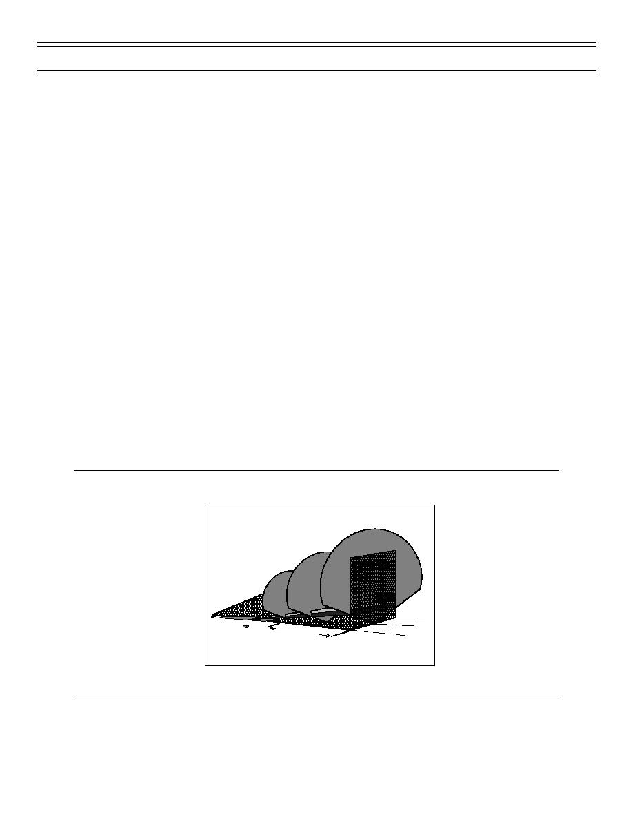
If the transmitted localizer beam, which usually, but not always, is directed in the heading of the runway extension. It does not appear during cruise, but comes up during the descent and approach to the selected runway, provided that the navigation radio is set to the ILS frequency of that specific runway. In modern cockpits, the localizer is seen as a colored dot (usually in the shape of a diamond) at the bottom of the artificial horizon gauge. Localizer is a combination of the beam system's narrow fan-shaped broadcasts with a modulation scheme that allows automated display, similar to VOR. Localizer in cockpitĪn Attitude Indicator, or perhaps more commonly known as the artificial horizon. See Instrument Landing System (ILS) Frequencies on even-numbered TACAN channels from 18X to 56Y. LOC carrier frequencies range between 108.10 MHz and 111.95 MHz (with the 100 kHz first decimal digit always odd, so 108.10, 108.15, 108.30, etc., are LOC frequencies and are not used for any other purpose). The LOC signal is in the 110 MHz range while the G/S signal is in the 330 MHz range. Localizer (LOC) and glide slope (G/S) carrier frequencies are paired so that the navigation radio automatically tunes the GS frequency which corresponds to the selected LOC frequency. These are transmitted from co-located antennas. One is modulated at 90 Hz, the other at 150 Hz. Two signals are transmitted on one of 40 ILS channels. Carrier frequency pairings for localizer and glide slope Some runways have ILS only in one direction, this can however still be used (with a lower precision) known as back beam. In parts of Africa and Asia large airports may lack any kind of transmitting ILS system. An older aircraft without ILS receiver cannot take advantage of any ILS facilities at any runway, and much more important, the most modern aircraft have no use of their ILS instruments at runways which lack ILS facilities. In aviation, a localizer is the lateral component of the instrument landing system (ILS) for the runway centreline when combined with the vertical glide slope, not to be confused with a locator, although both are parts of aviation navigation systems.Ī localizer (like a glideslope) works as a cooperation between the transmitting airport runway and the receiving cockpit instruments. 2 Carrier frequency pairings for localizer and glide slope.For each antenna type, a single horizontal antenna pattern is recommended for use in the frequency assignment process. This report compares measured and theoretical data with FAA antenna pattern specifications. The horizontal localizer antenna pattern now has a substantial effect on the separation required between localizer stations. In order to reduce siting effects, antenna patterns have evolved from the nearly omnidirectional 8-loop to the highly directional traveling wave and log periodic dipole antennas. ILS localizer antennas have undergone significant changes in recent years.

One of the factors which affects a station's signal strength in space is its horizontal antenna pattern. This is done by choosing frequencies in a manner which provides certain minimum cochannel and adjacent channel desired to undesired signal ratios at critical points of the service volume. The frequency assignment process is meant to insure interference-free service within the service volume. THE SELECTION OF ILS LOCALIZER ANTENNA PATTERNS FOR USE IN THE FREQUENCY ASSIGNMENT PROCESS


 0 kommentar(er)
